デザイン・ファイル
3 設計・ファイル
-
シミュレーションとモデル
DSP56321 IBIS Model File
-
シミュレーションとモデル
DSP56321 BSDL File PBGA196 Mask K91M
-
シミュレーションとモデル
DSP56321 BSDL File PBGA196 Mask K93M
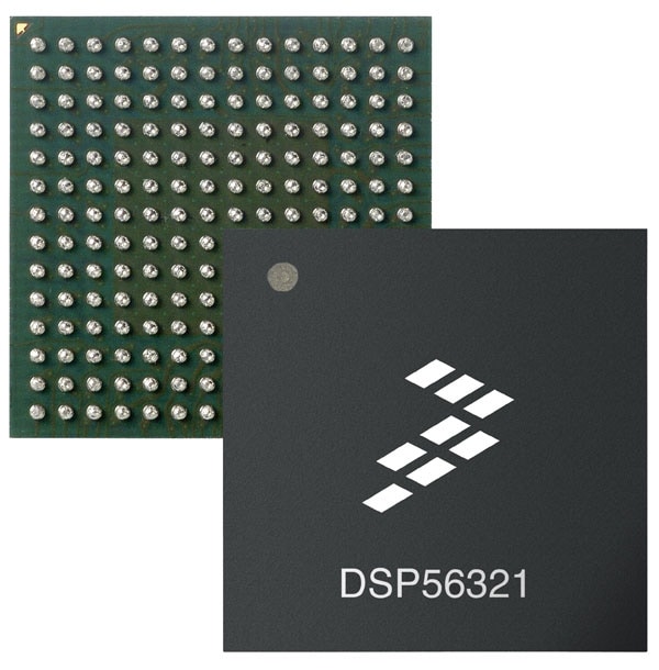
The DSP56321, a member of the DSP56300 family of programmable DSPs, supports network applications with general filtering operations. The on-chip enhanced filter coprocessor (EFCOP) executes filter algorithms in parallel with core operations to provide enhanced signal quality without affecting channel throughput or total number of channels supported, resulting in increased overall performance. Like the other family members, the DSP56321 uses a high-performance, single clock cycle per instruction engine, a barrel shifter, 24-bit addressing, instruction cache, and direct memory access (DMA) controller. The DSP56321 offers 275 million multiply accumulates per second (MMACS) performance (550 MMACS using the EFCOP in filtering applications) using an internal 275 MHz clock, a 1.6-volt core and independent 3.3-volt input/output (I/O).

Program RAM Size |
Instruction Cache Size |
X Data RAM Size* |
Y Data RAM Size* |
|---|---|---|---|
32 K x 24-bit |
0 |
80 K x 24-bit |
80 K x 24-bit |
31 K x 24-bit |
1024 x 24-bit |
80 K x 24-bit |
80 K x 24-bit |
40 K x 24-bit |
0 |
76 K x 24-bit |
76 K x 24-bit |
39 K x 24-bit |
1024 x 24-bit |
76 K x 24-bit |
76 K x 2 4-bit |
48 K x 24-bit |
0 |
72 K x 24-bit |
72 K x 24-bit |
47 K x 24-bit |
1024 x 24-bit |
72 K x 24-bit |
72 K x 24-bit |
64 K x 24-bit |
0 |
64 K x 24-bit |
64 K x 24-bit |
63 K x 24-bit |
1024 x 24-bit |
64 K x 24-bit |
64 K x 24-bit |
72 K x 24-bit |
0 |
60 K x 24-bit |
60 K x 24-bit |
71 K x 24-bit |
1024 x 24-bit |
60 K x 24-bit |
60 K x 24-bit |
80 K x 24-bit |
0 |
56 K x 24-bit |
56 K x 24-bit |
79 K x 24-bit |
1024 x 24-bit |
56 K x 24-bit |
56 K x 24-bit |
96 K x 24-bit |
0 |
48 K x 24-bit |
48 K x 24-bit |
95 K x 24-bit |
1024 x 24-bit |
48 K x 24-bit |
48 K x 24-bit |
112 K x 24-bit |
0 |
40 K x 24-bit |
40 K x 24-bit |
111 K x 24-bit |
1024 x 24-bit |
40 K x 24-bit |
40 K x 24-bit |
DSP56321クイック・リファレンス ドキュメンテーションの種類.
1-10 / 53 ドキュメント
コンパクトリスト
この選択アイテムには該当する結果がありません。
セキュアファイルの読み込み中、しばらくお待ちください。
1-10 の 54 ドキュメント
コンパクトリスト
3 設計・ファイル
セキュアファイルの読み込み中、しばらくお待ちください。
3 設計・ファイル