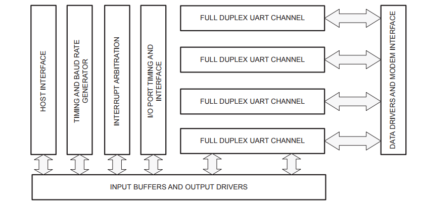
The Philips 28L194 Quad UART is a single chip CMOS-LSI communications device that provides 4 full-duplex asynchronous channels with significantly deeper 16 byte FIFOs, Automatic in-band flow control using Xon/Xoff characters defined by the user and address recognition in the Wake-up mode. Synchronous bus interface is used for all communication between host and QUART. It is fabricated in Philips state of the art CMOS technology that combines the benefits of low cost, high density and low power consumption.
The operating speed of each receiver and transmitter can be selected independently from one of 22 fixed baud rates, a 16X clock derived from one of two programmable baud rate counters or one of three external 16X clocks (1 available at 1x clock rate). The baud rate generator and counter can operate directly from a crystal or from seven other external or internal clock inputs. The ability to independently program the operating speed of the receiver and transmitter makes the Quad UART particularly attractive for dual speed full duplex channel applications such as clustered terminal systems. The receivers and transmitters are buffered with FIFOs of 16 characters to minimize the potential for receiver overrun and to reduce interrupt overhead. In addition, a handshaking capability and in-band flow control are provided to disable a remote UART transmitter when the receiver buffer is full or nearly so.
To minimize interrupt overhead an interrupt arbitration system is included which reports the context of the interrupting UART via direct access or through the modification of the interrupt vector. The context of the interrupt is reported as channel number, type of device interrupting (receiver COS etc.) and, for transmitters or receivers, the fill level of the FIFO.
The Quad UART provides a power down mode in which the oscillator is stopped but the register contents are maintained. This results in reduced power consumption of several orders of magnitudes. The Quad UART is fully TTL compatible when operating from a single +5V or 3.3V power supply. Operation at 3.3V or 5.0V is maintained with CMOS interface levels.
