デザイン・ファイル
2 設計・ファイル
-
シミュレーションとモデル
PCA9559 IBIS model
-
シンボルおよびフットプリント
PCA9559PW-TSSOP20-CAD Symbol and PCB Footprint – BXL File
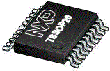
The PCA9559 is a 20-pin CMOS device consisting of one 6-bit non-volatile EEPROM registers, 5 hardware pin inputs and a 5-bit multiplexed output with one latched EEPROM bit. It is used for DIP switch-free or jumper-less system configuration and supports Mobile and Desktop VID Configuration, where 2 preset values (1 set of internal non-volatile registers and 1 set of external hardware pins) set processor voltage for operation in either performance or deep sleep modes. The PCA9559 is also useful in server and telecom/networking applications when used to replace DIP switches or jumpers, since the settings can be easily changed via I²C/SMBus without having to power down the equipment to open the cabinet. The non-volatile memory retains the most current setting selected before the power is turned off.
The PCA9559 typically resides between the CPU and Voltage Regulator Module (VRM) when used for CPU VID (Voltage IDentification code) configuration. It is used to bypass the CPU-defined VID values and provide a different set of VID values the VRM, if an increase in the CPU voltage is desired. An increase in CPU voltage combined with an increase in CPU frequency leads to a performance boost of up to 7.5pct. Lower CPU voltage reduces power consumption.
The PCA9559 has 2 address pins allowing up to 4 devices to be placed on the same I²C-bus or SMBus.

| | | | | |
|---|---|---|---|---|---|
| | | | | |
| | | | | |
| | | | | |
| | | | | |
| | | | | |
| | | | | |
| | | | | |
| | | | | |
| | | | | |
| | | | | |
クイック・リファレンス ドキュメンテーションの種類.
1-5 / 6 ドキュメント
There are no results for this selection.
サインイン 許可されたセキュアファイルにアクセス。について詳しくはこちら セキュアなアクセス権.
セキュアファイルの読み込み中、しばらくお待ちください。
1-5 の 6 ドキュメント
2 設計・ファイル
サインイン 許可されたセキュアファイルにアクセス。について詳しくはこちら セキュアなアクセス権.
セキュアファイルの読み込み中、しばらくお待ちください。
2 設計・ファイル