Getting Started with the MPC5748G Secure Ethernet Gateway reference design
このドキュメントの内容
-
Out of the Box
-
Get Software
-
Plug It In
-
Build and Load
サインイン 進行状況を保存するには アカウントをお持ちでない方 アカウントを作成する。

お客様の MPC5748G Secure Ethernet Gateway Reference Design
1. Out of the Box
1.2 Understanding the Connector Signals
| Connector | Description |
|---|---|
|
MATEnet Part No. 9-2305390-9 |
5-port 100BASE-T1 Ethernet connector. The RDB uses 4 ports as 100BASE-T1 Ethernet port |
| Part No. 2311621-1 | DoIP Port, 100BASE-TX with 4 PINs used for TX/RX |
| Part No. 2311622-1 |
8 x CAN/CAN FD channels: CAN0-CAN7 8 x 2 PINs |
| Part No. 2329531-1 |
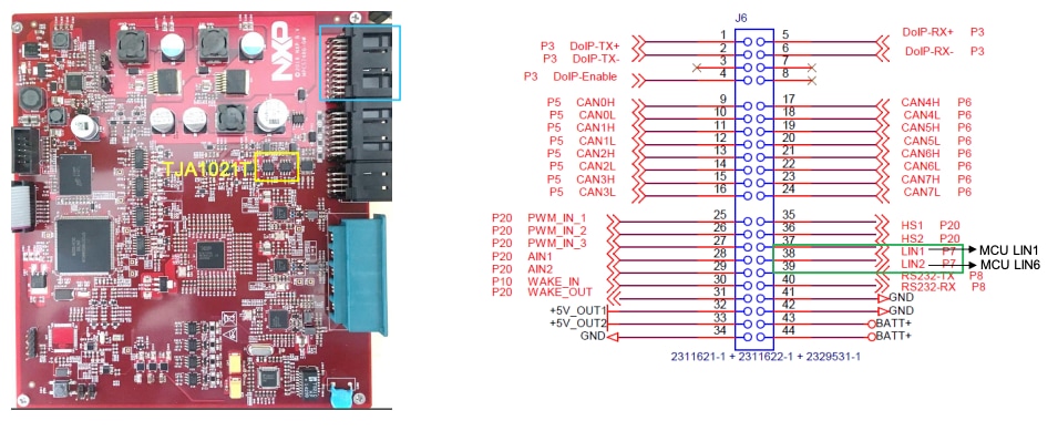
Used for power supply, LIN, UART, ADC, PWM, IO etc. 10 x 2 PINs |
2. Get Software
2.1 Download the MPC5748G-GW-RDB Reference Design – Software Package
You will use the example projects from this reference design.
2.2 Get Your Integrated Development Environment (IDE)
MPC5748G-GW-RDBperforms better when using S32 Design Studio for Power Architecture®.
DOWNLOAD S32 DESIGN STUDIO IDE
3. Plug It In
To set up your reference design board, watch the video or use the step-by-step guide, below.
Let’s take it for a test drive.
3.1 Set Up Jumpers in the S32K144EVB Evaluation Board
| Jumper | Setting | Description |
|---|---|---|
| J3 | Leave open. | Power SBC configuration. |
| J4 | 1-2 | Put the jumper on to enable SBC to reset MPC5748G. Refer to the schematics for more details. |
| J5 | 1-2 |
Put the jumper on to set SBC into DEBUG mode. In this mode, SBC will work as a common power supplier. Check Power Management Integrated Circuits and System Basis Chips for more details. |
| J12 | 1-2 | Put the jumper on to enable User Switch to reset MPC5748G |
| J13 | Leave open. | This jumper can enable User Switch to reset S32K. Keep it open and do not use this Jumper. |
4. Build and Load
4.1 Create a New Project in IDE
Watch the video to create a new project in S32 Design Studio IDE and load a code example or, use the step-by-step guide, below.
Launch the S32 Design for Power Architecture and select a default workspace or specify a new one. Then click "OK".

Create a new project by selecting File > New > Project.

Choose a project name and then select a project type, then click "Next". We recommend using Elf S32DS Project for this one.

Select cores and parameter, then click "Finish".
Make selections in FLASH and RAM Size, Language, Library and Debugger
.We recommend using defaults settings for now.

Three projects will be created for three different cores of MPC5748G.

4.2 Build a New Project in IDE
Follow one of these paths to build a new project:
- Project > Build Project
- Click the
 to build the project.
 - Then click
 to build all projects.

The following message displays on the console once you have successfully built a project:

4.3 Debug a Project in IDE
Connect the PE micro debugger to both the board and PC.
Open the Debug Configuration options at the top menu.
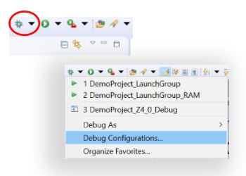
- Select Project to debug.
- Select the Interface:
USB Multilink, USB Multilink FX… - Select the Port:
USB1-Multilink Universal Rev C… - Click Debug to start.

4.4 Debug a Project from RAM
Follow one of these paths to configure a project to debug from RAM:
-
Go to Project > Build Configurations > Set Active > Debug_RAM
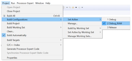
-
Select Debug_RAM by clicking down the arrow next to the "gear" icon

Finally, select the RAM-related session while debugging.

Learn more about debugging basics at Projects and Tutorials.
Installing S32 Design Studio IDE (S32DS) for Power Architecture
Download the latest version of our S32 Design Studio IDE for Power Architecture.
-
Go to the download folder. Run the installation file, the "Preparing to install dialogue box" will appear

-
When the installer wizard window is displayed, click "Next"

-
Selecting the "S32 Design Studio" only installs this software. To install more software, select "Additionally install" option.
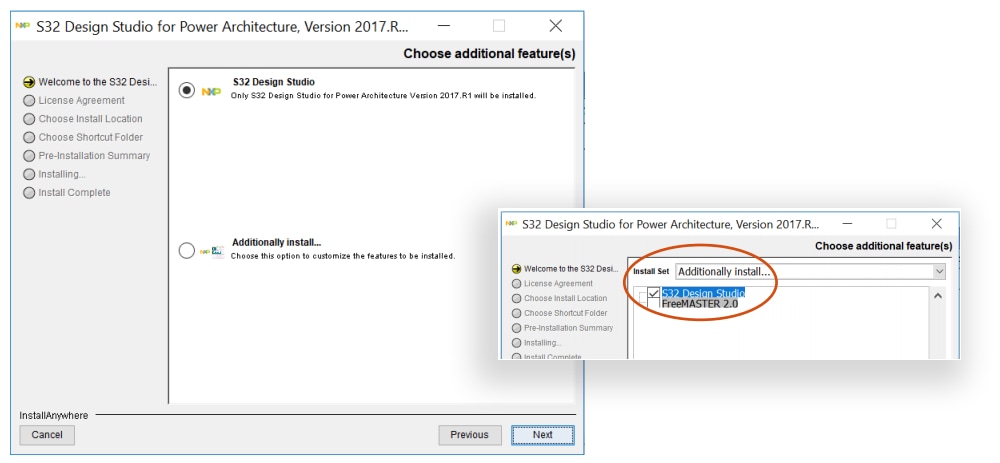
-
We recommend you to entirely read the License Agreement
Once done, select the radio button accepting the agreement terms and click "Next" to continue
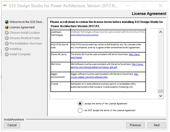
-
Choose either the default or new installation location, then click "Next".

-
Select a path to generate a shortcut of your choice and click "Next".

-
Verify all settings in the "Pre-installation Summary" tab
-
If everything is accurate, click "Install".

At some point during the installation, you will be prompted for the software activation code
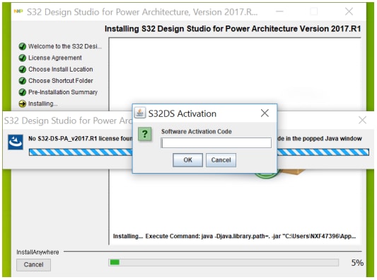
To get your activation code, go to the "Product Download" page and select the "License Keys" tab.
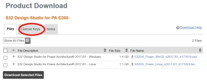
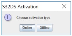
Copy and paste the software activation code into the activation window, then select "Online".
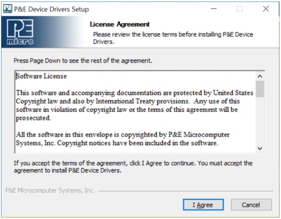
During installation, you need to download the P&E device drivers. Read the license agreement and click "I agree".
Then select the destination folder and click "Install". When the installation is complete, click "Close".
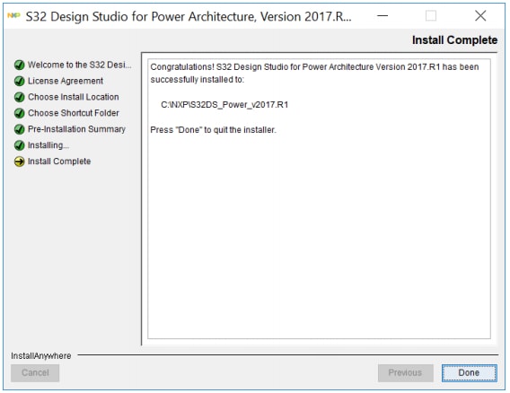
You will see an "Install Complete - Congratulations" message in the installer wizard window once the S32 Design Studio for Power Architecture installation is complete.
Updating S32DS IDE for Power Architecture with SDK (RTM)
Get the SDK RTM 1.0.0 update from the S32DS IDE for Power Architecture page.

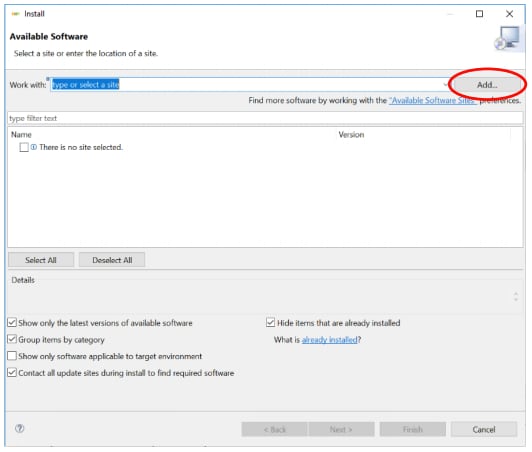
Launch S32DS and go to Help > Install New Software.
Click "Add" in the Install wizard window to find the SDK which has been downloaded.
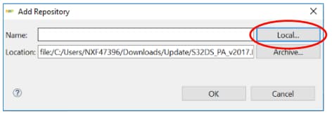
Click "Local" to add repositories in the "Add Repository" window. Then click "OK".
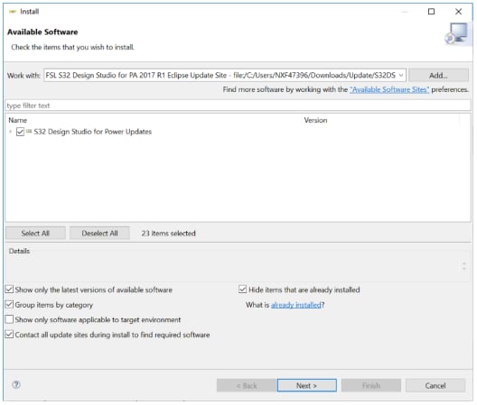
Check the S32 Design Studio for Power Updates and then click "Next".
Read all the license terms and click "Finish".
We recommend you to entirely read the License Terms and click "Finish" to continue.

The SDK (RTM) installation will immediately start.
In "Do you trust these certificates?" check the checkbox and click "OK".



Success
Once the installation is complete, restart your S32DS IDE.
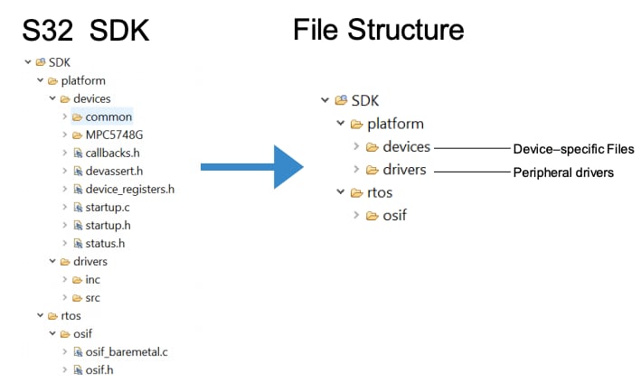
S32SDK Overview
S32 Software Development Kit (SDK)
- Integrated non-AUTOSAR software production-grade software
- Automotive grade: SPICE/CMMI compliant, MISRA 2012
- Graphical-based configuration and layered software architecture
- Integrated with S32 Design Studio, plus FreeRTOS
- Compatible with Eclipse and other IDEs
- Supports MPC574x family, also multiple toolchains
- Documented source code, including examples and demos
Debug Basics
Step, Run, Suspend, Resume and Terminate
- Step Into (F5)
- Step Over (F6)
- Run
- Suspend
- Resume (F8)
- Terminate (Ctrl + F2)
- To View Variables:
- Open the "Variables" tab.
- Click on a value to allow typing in a different value.
- To View and Alter Registers:
- To see CPU registers, select the "Registers" tab.
- Click on a value to allow typing in a different value.
- To view peripheral registers in the EmbSysReg tab.
- To View and Add Memory:
- To add memory monitor, click the + icon and select Base Address (EXAMPLE: 0x0000fff8)
- This allows you to view memory.
- To Add Breakpoints:
- Select and double click.


Code Examples: Hands-on – CAN

Resources
- Full implementation of the CAN FD and CAN 2.0 B: data field bitrate up to 8 Mbps
- Flexible mailboxes (0/8/16/32/64 bytes data length)
- Listen-Only mode capability
- Programmable loop-back mode supporting self-test operation
- Programmable transmission priority scheme
- Programmable clock source to the CAN protocol interface, either bus clock or crystal oscillator
- Independence from the transmission medium
- CRC status for transmitted message
- Full featured Rx FIFO with storage capacity for 6 frames
- DMA request for Rx FIFO
- 100% backward compatibility with previous FlexCAN version
- 8 FlexCAN instances
CAN: Import Existing Project
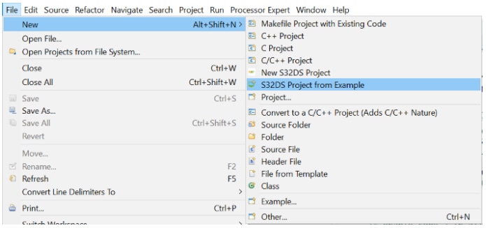
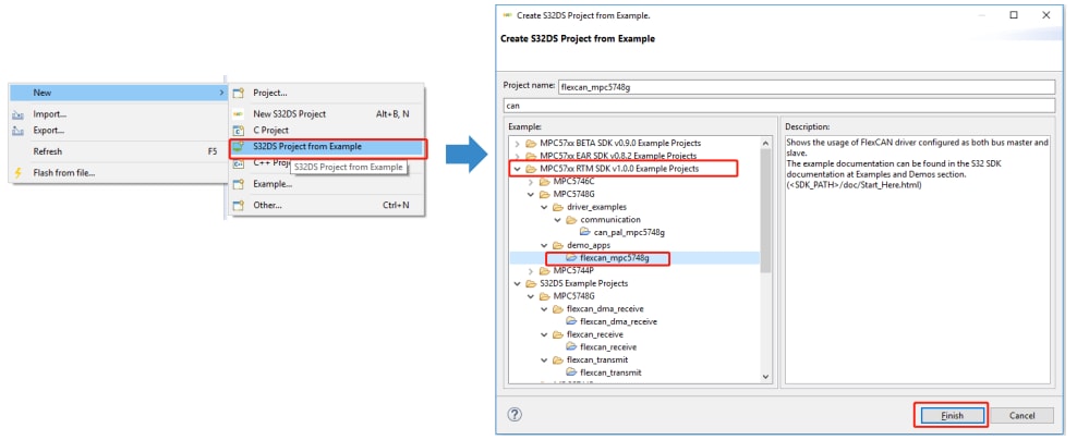
Go to File > New > New S32DS Project from Example to create a new S32 Design Studio project.
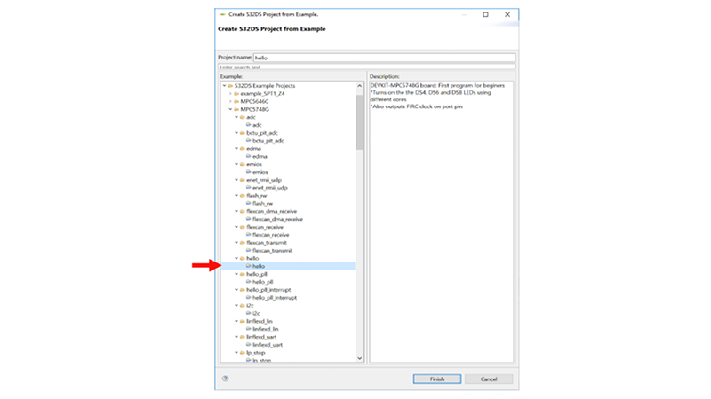
Then select the flexcan_mpc5748g file from the MPC57xxRTM SDK v1.0.0 Example Projects folder.
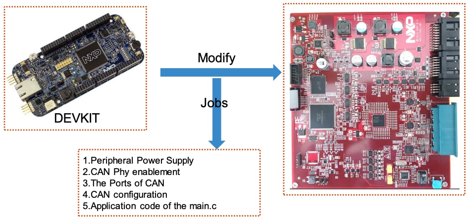
CAN: Modify
The flexcan_mpc5748g example project is suited to DEVKIT.
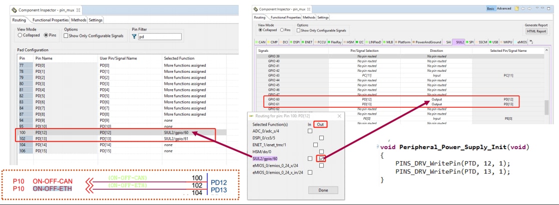
To modify the peripheral power supply: enable the peripheral power supply
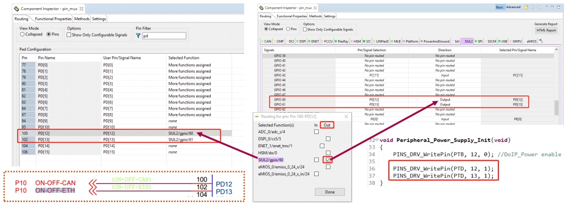
Open pin_mux component in "Component Inspector" to configure pin routing:
SIUL2 tab > GPIO 60 and GPIO 61 and then select the pin (one option) + direction output.
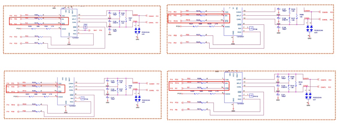
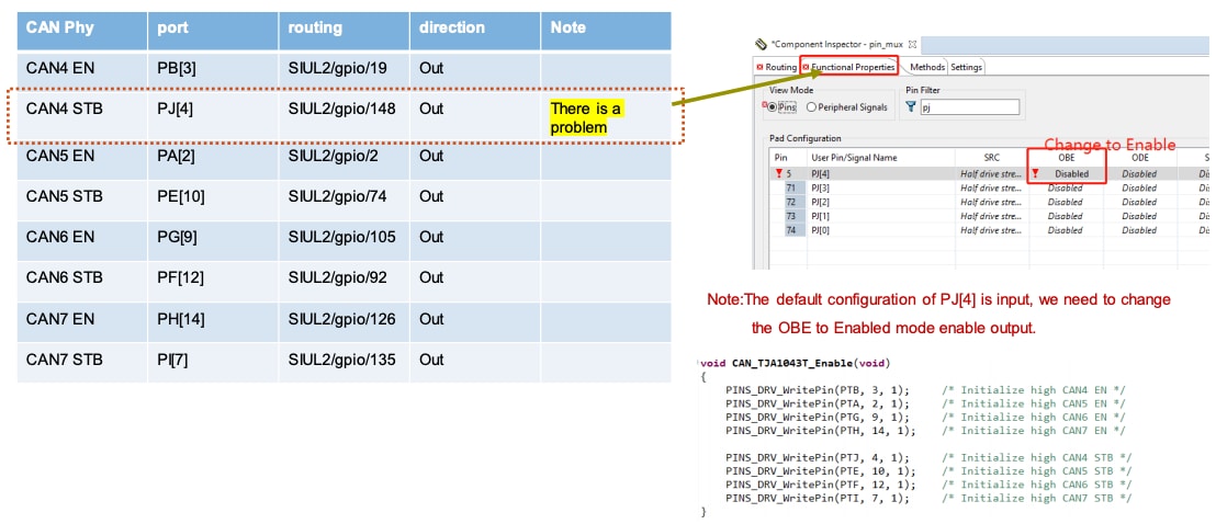
To modify the CAN Phy enablement: configure the CAN4~7 Phy (TJA1043T) GPIO
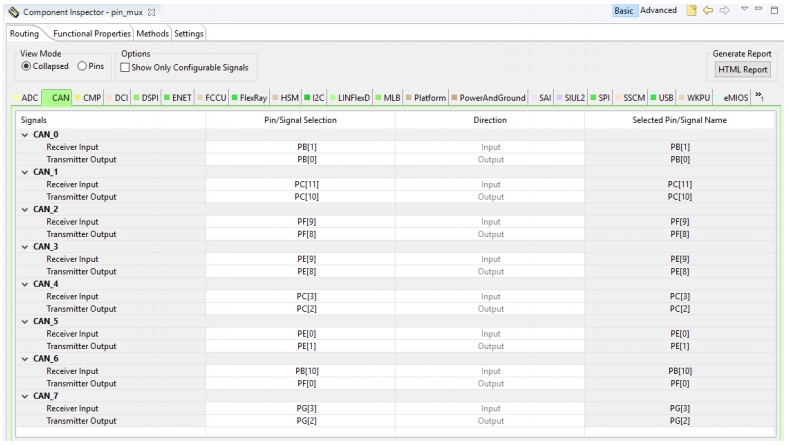
To modify the CAN ports, go to "Routing" (collapsed) in in pin_mux component, then select "CAN". Configure the ports according to the schematic.
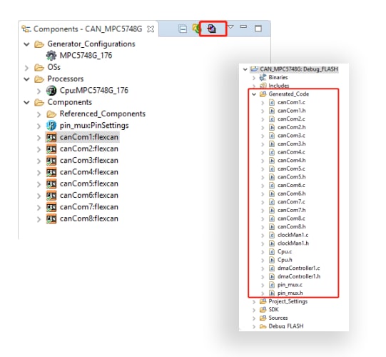
To modify the CAN configuration
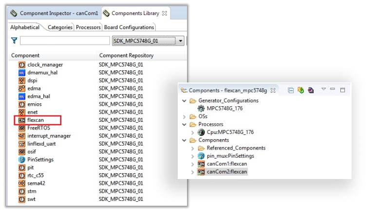
Under the Components Library tab view, double-click flexcan component to add it the project.
There is no need to change default configuration for CAN: standard CAN (no FD), minimum payload, 500 kbps
Once all CAN configurations are complete, click "Generate code".
CAN: Application Code
Open the main.c file in text editor view.
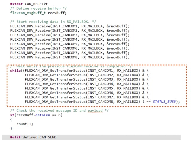
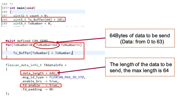
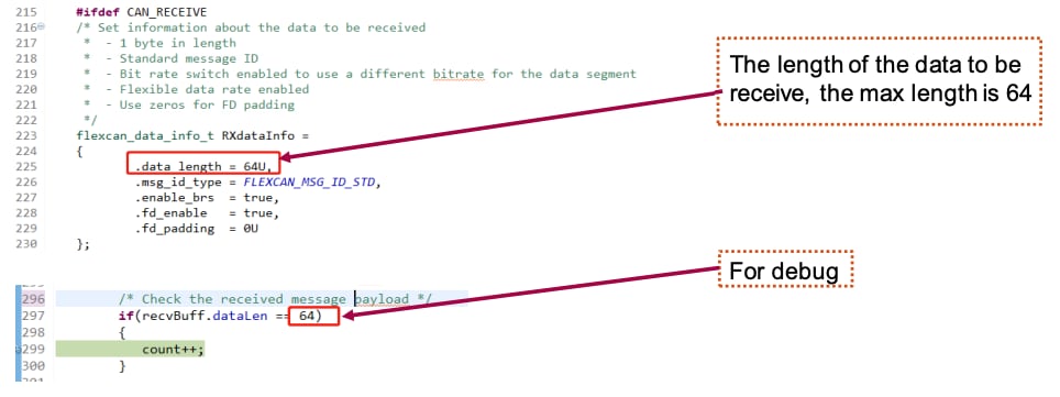
The sending and receiving function of this project is realized separately, which needs to be controlled by macros.
Peripheral Power Supply
CAN4~CAN7'S Phy (TJA1043T) Enable
Sending data via CAN
Receiving data via CAN
CAN: Build and Debug
Make sure that there are no compilation errors, then click build project.
Select the correct debug configuration and interface to debug the application.
TEST: Sending data via CAN
- Open the macro of
CAN_SEND, commented outCAN_RECEIVE - Connect the sending port with
PEAK(the test tools we use) through the wire. - Debug the application.
TEST: Receiving data via CAN
- Open the macro of
CAN_RECEIVE, commented outCAN_SEND - Connect the receiving port with PEAK (the test tools we use) through the wire.
- Debug the application
Code Examples: Hands-on – CAN FD
CAN FD is configured similarly to CAN.
Check the Projects and Tutorials > Hands-on – CAN to learn how to modify the CAN configurations and the application code of
main.c
CAN FD: Modify Configuration
To change default configuration for CAN FD:
standard CAN_FD, maxmum payload, Arbitration Phase: 500 kbps,
Data Phase: 2000 kbps
CAN FD: Build and Debug
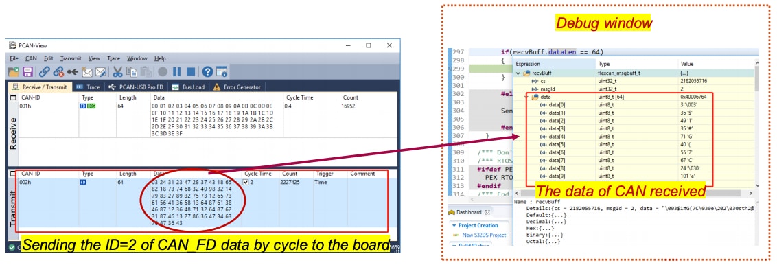
TEST: Sending data via CAN FD
- Open the macro of
CAN_SEND, commented outCAN_RECEIVE - Connect the sending port with
PEAK(the test tools we use) through the wire - Debug the application
TEST: Receiving data via CAN
- Open the macro of
CAN_RECEIVE, commented outCAN_SEND - Connect the receiving port with PEAK (the test tools we use) through the wire
- Debug the application
Code Examples: Hands-On – ENET0+SPI
Resources
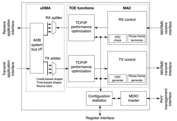
- The core implements a dual-speed 10/100 Mbit/s Ethernet MAC compliant with the IEEE802.3-2002 standard. The MAC layer provides compatibility with half- or full-duplex 10/100 Mbit/s Ethernet LANs.
- The MAC operation is fully programmable and can be used in network interface card (NIC), bridging or switching applications. The core implements the remote network monitoring (RMON) counters according to IETF RFC 2819.
- The programmable Ethernet MAC with IEEE 1588 integrates a standard IEEE 802.3 Ethernet MAC with a time-stamping module. The IEEE 1588 standard provides accurate clock synchronization for distributed control nodes for industrial automation applications.
- Full-duplex, three-wire synchronous transfers
- Leader mode
- Follower mode
- Data streaming operation in follower mode with continuous follower selection
- Buffered transmit operation using the transmit first in first out (TX FIFO) with depth of 4 entries
- Support for 8/16-bit accesses to the PUSH TX FIFO register data field
- Buffered receive operation using the receive FIFO (RX FIFO) with depth of 4 entries
- Asynchronous clocking scheme for register and protocol interfaces
- TX and RX FIFOs can be disabled individually for low-latency updates to SPI queues
- Visibility into TX and RX FIFOs for ease of debugging
- 6 peripheral chip selects (PCSes), expandable to 64 with external demultiplexer
- Deglitching support for up to 32 peripheral chip selects (PCSes) with external demultiplexer
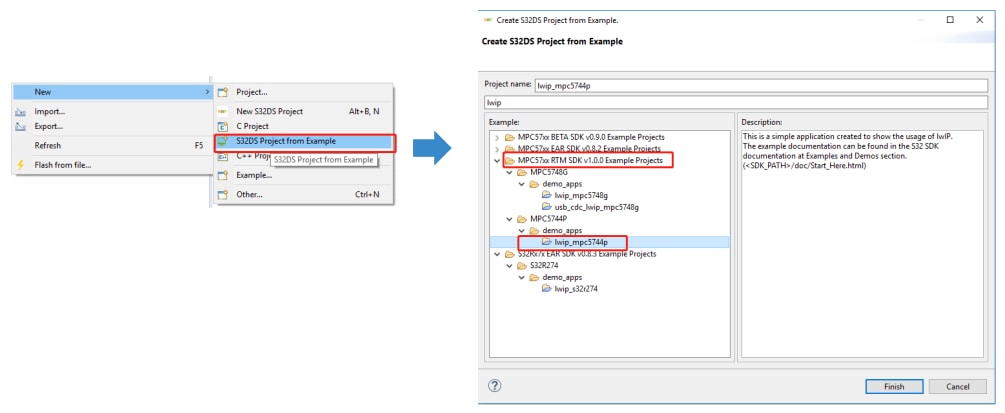
ENET0: Import Existing Project
Go to File > New > New S32DS Project from Example to create a new S32 Design Studio project.
Then select the lwip_mpc5748g file from the "MPC57xxRTM SDK v1.0.0 Example Projects" folder.
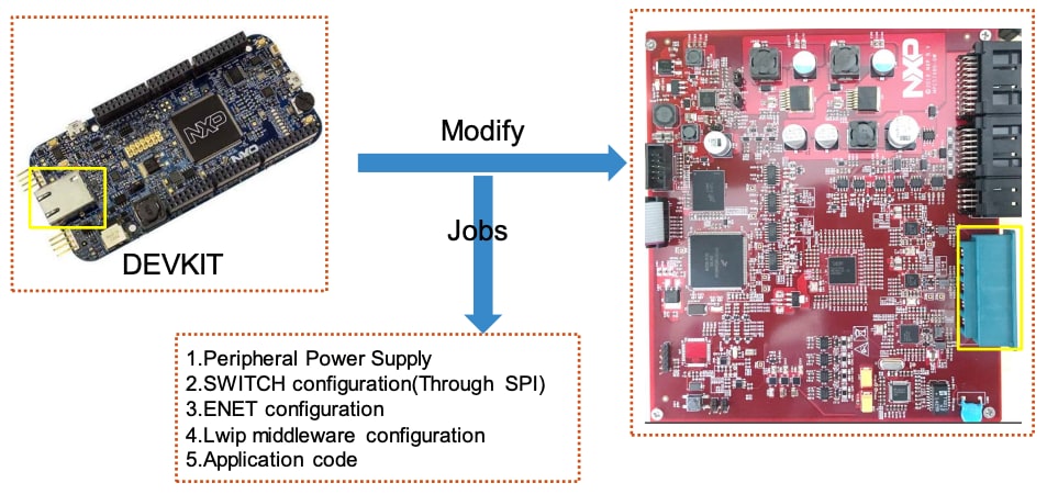
ENET0: Modify
The flexcan_mpc5748g example project is suited to DEVKIT.
To modify and enable the peripheral power supply:
Open pin_mux component in "Component Inspector" to configure pin routing:
SIUL2 tab > GPIO 60 and GPIO 61 and then select the pin (one option) + direction output.
ENET0: SWITCH configuration
Add spi_pal component in the "Components Library" tab, then double click the component to add it the project.
For the SPI configuration port, go to, "Routing" (Collapsed) in pin_mux component, then select SPI.
Configure the ports according to the schematic.
SPI component configuration:
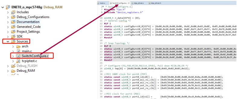
The tool for configuring SWITCH data structure is: sja1105_tools
Check the sample demo (the ENET0_MPC5748G project) and copy the SwitchConfigure.c file to
your project without any modification.
ENET0: ENET configuration
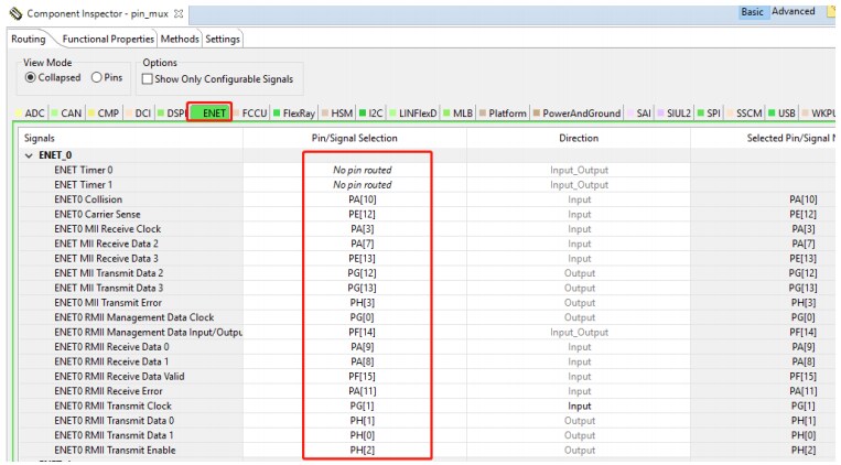
Go toRouting (Collapsed) in pin_mux component, then select "ENET".
Configure the ports according to the schematic.
ENET0: lwip middleware configuration
ENET0: Application Code
Peripheral power supply: [Project Name] > Source > main.c
To Modify the configuration of SPI to adaptation SJA1105 go to: [Project Name] > SDK > platform > pal > spi > src >
spi_pal.c
The default configuration of SPI`s CS pin cannot be maintained until the delivery is completed when the send function ( SPI_MasterTransferBlocking() ) is called.
In order to match the SWITCH, configure the dspiConfig.continuousPCS = true
To add the initialization of the SWITCH, go to: [Project Name] > SDK > middleware > tcpip > tcpip_stack > demo > test.c.
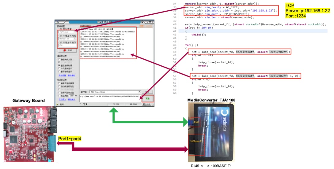
Add client application for lwip_tcp.
Check the sample demo (the ENET0_MPC5748G project) and copy the tcpiptest.c file to your
project without any modification.
Add client application call function under [Project Name] > SDK > middleware > tcpip > tcpip_stack > demo >test.c
Code Examples: Hands-On – ENET1
ENET1 is configured similarly to ENET0.
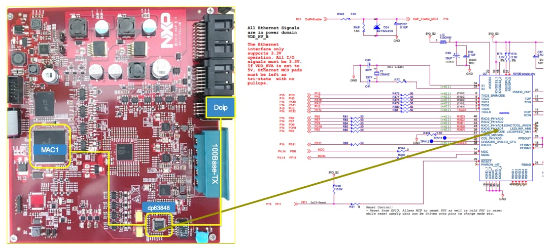
Unlike the previous section, the Phy (DP83848) for MCA1 is directly connected.
Check the Projects and Tutorials > Hands-on – ENET0+SPI.
Resources:
ENET1: Modify
To enable and modify the peripheral power supply:
Open pin_mux component in "Component Inspector" to configure pin routing:
SIUL2 tab > GPIO 60 and GPIO 61 and then select the pin (one option) + direction output.
ENET1: DP83848 Configuration
Initialize the DoIP-Reset pin - Initialize to high level:
Enable the DoIP Phy`s power.
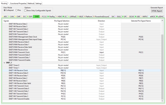
ENET1: ENET Configuration
Go to Routing (Collapsed) in pin_mux component, then select "ENET".
Configure the ports according to the schematic:
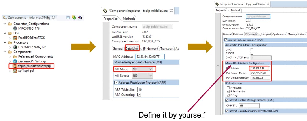
ENET1: lwip middleware configuration:
ENET1: Application Code
For the peripheral power supply, go to: [Project Name] > Source > main.c
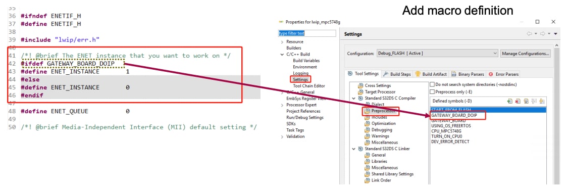
To fix a problem in the SDK, go to: [Project Name] > SDK > middleware > tcpip > tcpip_stack > ports > netif > enetif > enetif.h
The SDK only implements the configuration for MAC0, and the code shown needs to be added to support MAC1.
If there is an issue with the code generated for the ENET1 GPIO configuration:
Check the sample demo (the project of ENET1_MPC5748G project) and copy the
Enet1IOConfigure.c file to your project without any modification.
To add the client application for lwip_tcp.
Check the sample demo (the project of ENET0_MPC5748G project) and copy the
tcpiptest.c file to your project without any modification.
Add client application call function under [Project Name] > SDK > middleware > tcpip > tcpip_stack > demo > test.c.
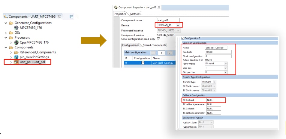
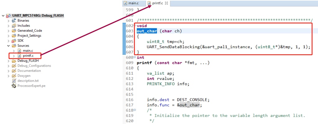
Code Examples: Hands-On – UART
- Full-duplex communication
- Separate clock for baud rate calculation
- The relationship “(2/3)* LIN_CLK > PBRIDGEx_CLK > 1/3*LIN_CLK” should be maintained.
- 15/16/7/8 bits data, parity
- 1/2/3 stop bits
- 12-bit + parity reception, 12-bit counter for timeout management
- 4-byte buffer for reception, 4-byte buffer for transmission
- The maximum baud rate achievable is LIN_CLK/4 Mbit/s.
- For bit rate ≤ LIN_CLK/16 Mbit/s
- Sixteen times oversampling
- 3:1 majority voting for LIN_CLK/16 Mbit/s < bit rate < LIN_CLK/8 Mbit/s
- Reduced over sampling programmable by the user
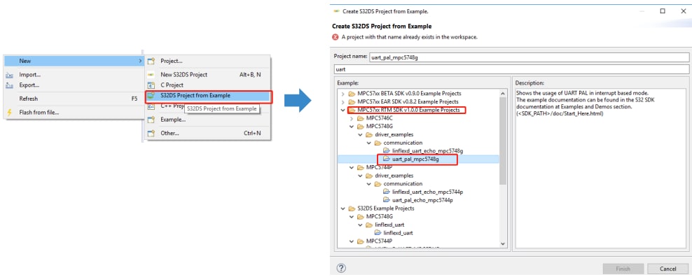
UART: Import Example Project
Go to File > New > New S32DS Project from Example to create a new S32 Design Studio project.
Then select the uart_pal_mpc5748g file from the "MPC57xxRTM SDK v1.0.0 Example Projects" folder.
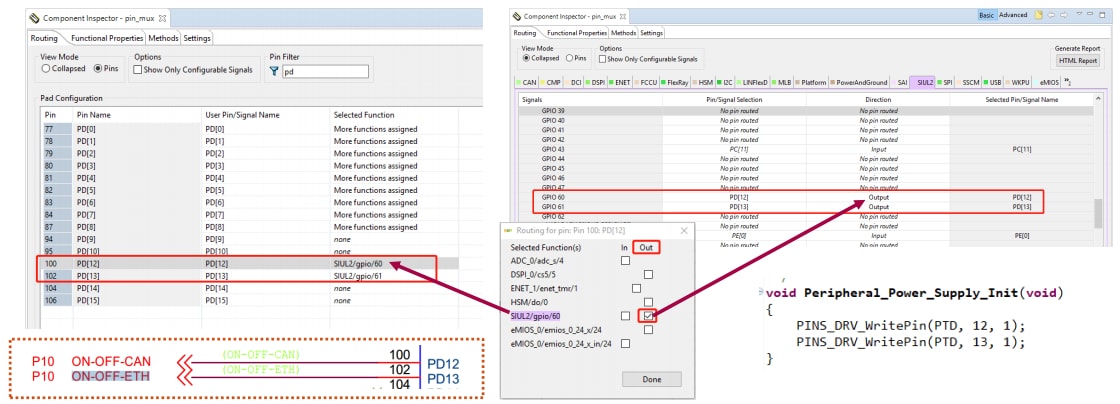
UART: Modify
To enable and modify the peripheral power supply:
Open pin_mux component in "Component Inspector" to configure pin routing:
SIUL2 tab > GPIO 60 and GPIO 61 and then select the pin (one option) + direction output.
Code Examples: Hands-On – LIN
- Supports LIN protocol version 1.3, 2.0, 2.1 and 2.2
- Bit rates up to 20 Kbit/s (LIN protocol)
- Leader/follower mode
- Classic and enhanced checksum calculation and check
- Single 8-byte buffer or FIFO for transmission/reception
- Timeout management
- Identifier filters
- DMA interface
- Supports a maximum of 16 possible identifiers
- Leader mode with autonomous message handling
- Wakeup event on dominant bit detection
- True LIN field state machine
- Advanced LIN error detection
- Header, response and frame timeout
- Follower mode
- Autonomous header handling
- Autonomous transmit/receive data handling
- Identifier filters for autonomous message handling in follower mode
- Separate clock for baud rate calculation
- The relationship “(2/3)* LIN_CLK > PBRIDGEx_CLK > 1/3*LIN_CLK” should be maintained.
Resources: on-board user LIN ports (hardwired to GPIOs)
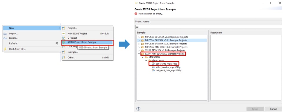
Code Examples: Hands-On – eMMC+Fatfs
Make sure that your SDK has been upgraded to RTM2.0.0.
eMMC+Fatfs: Import Example Project
Import the example code within the SDK from File > New > New S32DS Project from Example.
Select the sdhc_fatfs_mpc5748g file from the "MPC57xxRTM SDK v2.0.0 Example Projects".
eMMC+Fatfs: Modify
To modify the peripheral power supply, first enable it.
Open pin_mux component in "Component Inspector" to configure pin routing:
SIUL2 tab > GPIO 60 and GPIO 61 and then select the pin (one option) + direction output.
このページ
- 2.1
Download the MPC5748G-GW-RDB Reference Design – Software Package
- 2.2
Get Your Integrated Development Environment (IDE)
- 2.3
Get Your Software Development Kit (SDK)
- 3.1
Set Up Jumpers in the S32K144EVB Evaluation Board
- 3.2
Plug in the Cables and Debugger
- 3.3
Plug In the 12 V Power Supply
- 4.1
Create a New Project in IDE
- 4.2
Build a New Project in IDE
- 4.3
Debug a Project in IDE
- 4.4
Debug a Project from RAM
- 4.5
Make Projects from Built-In Examples
- 4.6
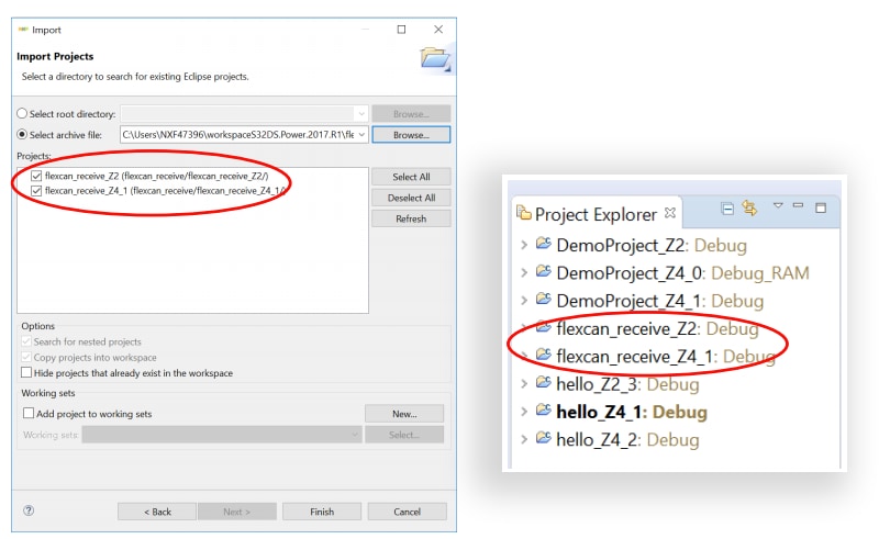
Import Projects into IDE
- Resources
- ENET0: Lab Preview
- ENET0: Import Existing Project
- ENET0: Modify
- ENET0: SWITCH configuration
- ENET0: ENET configuration
- ENET0: Application Code
- ENET0: Build and Debug
- ENET1: Modify
- ENET1: DP83848 Configuration
- ENET1: ENET Configuration
- ENET1: Application Code
- ENET1: Build and Debug


