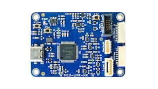
Motion Control 32-bit Microcontroller based on Arm® Cortex®-M3

製品画像を見る

Features

System

  • Arm Cortex-M3 processor, running at frequencies of up to 72 MHz.
  • ARM Cortex-M3 built-in Nested Vectored Interrupt Controller (NVIC).
  • System tick timer.
  • Serial Wire Debug (SWD) with four breakpoints and two watchpoints.
  • Single-cycle multiplier supported.
  • Memory Protection Unit (MPU) included.

Memory

  • Up to 64 kB on-chip flash programming memory with 256 Byte page write anderase.
  • Up to 12 kB SRAM.
  • 4 kB EEPROM.

ROM API support

  • Boot loader with boot options from flash or external source via USART, C_CAN or USB.
  • USB drivers
  • ADC drivers.
  • SPI drivers.
  • USART drivers.
  • I²C drivers.
  • Power profiles and power mode configuration with low-power mode configurationoption.
  • DMA drivers.
  • C_CAN drivers.
  • Flash In-Application Programming (IAP) and In-System Programming (ISP).

Digital peripherals

  • Simple DMA engine with 18 channels and 20 programmable input triggers.
  • High-speed GPIO interface with up to 44 General-Purpose I/O (GPIO) pins withconfigurable pull-up/pull-down resistors, open-drain mode, input inverter, andprogrammable digital glitch filter.
  • GPIO interrupt generation capability with boolean pattern-matching feature on eightexternal inputs.
  • Two GPIO grouped port interrupts.
  • Switch matrix for flexible configuration of each I/O pin function.
  • CRC engine.
  • Quadrature Encoder Interface (QEI).

Configurable PWM/timer/motor control subsystem

  • Up to four 32-bit counter/timers or up to eight 16-bit counter/timers or combinationsof 16-bit and 32-bit timers.
  • Up to 28 match outputs and 22 configurable capture inputs with input multiplexer.
  • Dither engine for improved average resolution of pulse edges.
  • Four State Configurable Timers (SCTimers) for highly flexible, event-driven timingand PWM applications.
  • SCT Input Pre-processor Unit (SCTIPU) for processing timer inputs and immediatehandling of abort situations.
  • Integrated with ADC threshold compare interrupts, temperature sensor, and analogcomparator outputs for motor control feedback using analog signals.

Special-application and simple timers

  • 24-bit, four-channel, multi-rate timer (MRT) for repetitive interrupt generation at upto four programmable, fixed rates.
  • Repetitive interrupt timer for general purpose use and use with debugtime-stamping.
  • Windowed Watchdog timer (WWDT).
  • High-resolution 32-bit Real-time clock (RTC) with selectable 1 s or 1 ms timeresolution running in the always-on power domain. RTC can be used for wake-upfrom all low power modes including Deep power-down.

Analog peripherals

  • Two 12-bit ADC with up to 9/7 input channels per ADC and with multiple internaland external trigger inputs and sample rates of up to 2 Msamples/s. Each ADCsupports two independent conversion sequences. ADC conversion clock can bethe system clock or an asynchronous clock derived from one of the three PLLs.
  • One 12-bit DAC.
  • Integrated temperature sensor and band gap internal reference voltage.
  • Four comparators with external and internal voltage references (ACMP0 to 3).Comparator outputs are internally connected to the SCTimer/PWMs and ADCs andexternally to pins. Each comparator output contains a programmable glitch filter.

Serial interfaces

  • Three USART interfaces with DMA, RS-485 support, autobaud, and withsynchronous mode and 32 kHz mode for wake-up from Deep-sleep andPower-down modes. The USARTs share a fractional baud-rate generator.
  • Two SPI controllers.
  • One I²C-bus interface supporting fast mode and Fast-mode Plus with data rates ofup to 1Mbit/s and with multiple address recognition and monitor mode.
  • One C_CAN controller.
  • One USB 2.0 full-speed device controller with on-chip PHY.

Clock generation

  • 12 MHz internal RC oscillator trimmed to 1 % accuracy for -25 °C ≤ Tamb ≤ +85 °Cthat can optionally be used as a system clock.
  • Crystal oscillator with an operating range of 1 MHz to 25 MHz.
  • Watchdog oscillator with a frequency range of 503 kHz.
  • 32 kHz low-power RTC oscillator with 32 kHz, 1 kHz, and 1 Hz outputs.
  • System PLL allows CPU operation up to the maximum CPU rate without the needfor a high-frequency crystal. May be run from the system oscillator or the internalRC oscillator.
  • Two additional PLLs for generating the USB and SCTimer/PWM clocks.
  • Clock output function with divider that can reflect the crystal oscillator, the mainclock, the IRC, or the watchdog oscillator.

Power control

  • Integrated PMU (Power Management Unit) to minimize power consumption.
  • Reduced power modes: Sleep mode, Deep-sleep mode, Power-down mode, and Deep power-down mode.
  • APIs provided for optimizing power consumption in active and sleep modes and for configuring Deep-sleep, Power-down, and Deep power-down modes.
  • Wake-up from Deep-sleep and Power-down modes on activity on USART,SPI, and I²C peripherals.
  • Wake-up from Sleep, Deep-sleep, Power-down, and Deep power-down modes from the RTC alarm or wake-up interrupts.
  • Timer-controlled self wake-up from Deep power-down mode using the RTChigh-resolution/wake-up 1 kHz timer.
  • Power-On Reset (POR).
  • BrownOut Detect BOD).

Additional features

  • JTAG boundary scan modes supported.
  • Individual device serial number for identification.
  • Single power supply 2.4 V to 3.6 V.
  • Temperature range -40 °C to +105 °C.
  • Available as LQFP64 package.

Target Applications

  • Motor control
  • Motion drives
  • Digital power supplies
  • Solar inverters
  • Home appliances
  • Building and factory automation
  • Industrial and medical

購入/パラメータ


ドキュメント

クイック・リファレンス ドキュメンテーションの種類.

1-5 の 11 ドキュメント

全て表示

デザイン・ファイル

クイック・リファレンス 設計・ファイルの種類.

4 設計・ファイル

ハードウェア

クイック・リファレンス ボードタイプ.

1-5 の 7 ハードウェア提供

全て表示

ソフトウェア

クイック・リファレンス ソフトウェア・タイプ.

1-5 の 11 ソフトウェア提供

全て表示

トレーニング

5 トレーニング

サポート

お困りのことは何ですか??